Colouring an Icosahedron
15th August 2020

Contents
I think that modular origami is my favourite type of origami. You can start with something quite simple, practise it a lot, and still end up with quite a nice single model at the end (rather than paper boxes). Mind you, my introduction to it was the interlocking tetrahedra which isn't the easiest of models to make!
A few years ago, I came across a book called Zen Origami which has lots of very nice modules to make and which comes with its own set of lovely paper. When I first got it, I happily made icosahedra and dodecahedra and other-ahedra with a single design of paper for each.
Then I started to reach the end of the stack of paper and could no longer pick a single design for a model but had to use more than one design. This led to the question as to how to allocate the designs. One option is clearly "at random", but I wanted to have some more structure than that.
Enter a little group theory.
The idea is to look for symmetry when choosing the designs. The symmetries of the model will interact with the choices, some in a good way and some not. The goal is to allocate the designs so that there are as many "good" symmetries as possible1.
1Sometimes one wants to break the symmetry deliberately but to do this one needs to know what the symmetry is beforehand.
Although the motivating problem is of choosing paper designs for an origami model, the language I'm going to use is of colours because it makes for easier pictures. Obviously to go back to the origami, we pick a paper design to correspond to each colour (though there is scope for a little more variation as the designs themselves may not be symmetrical on the paper). Or just use monochrome paper.
The other thing to get straight at the outset is that for most models the modules form the edges of the final polyhedron. So we are colouring the edges of a model. It can be useful at times to think of it as a wireframe model rather than a solid. Indeed, some modules leave holes in the centres of the faces, others fill them in, still others form stellations on those faces, but ultimately each module corresponds to an edge of the model. One consequence of this is that there is no distinction between solving the problem for a polyhedron and for its dual. Among Platonic solids, therefore, there are only three cases to consider. I'll focus on these, though the techniques apply to any polyhedron.
My goal in this is to show how I went about using a little group theory to figure out how to use up my paper odds and ends. The focus was very much on finding a nice design and not on figuring out a complete solution for every polyhedron.
Another thing that I don't talk about is choosing the modules. Although each module corresponds to an edge in the model, it isn't always obvious which edge a particular module relates to due to how it is in front or behind other modules. If the aim is to show off some symmetry of the polyhedron, I would recommend thinking carefully about how the colours (or paper designs) will be seen in the final model. I have made some models using a symmetry principle in which the symmetry was not evident at all because the module that I chose scattered the design across multiple edges.
1 A Bit of Formality
In this section I want to formalise the notions I'll be working with, which is code for "feel free to skip this section".
We have a polyhedron, , and its symmetry group . This polyhedron has a set of edges, , and we write for the group of permutations of these edges thought of as just a set (so, ignoring any positional information). Applying symmetries to the polyhedron defines a group homomorphism .
A colouring of the edges is a partition of the set of edges. That is, a family of subsets of the edges with the property that their union is the whole set and they are pairwise disjoint. Let us write for the set of colourings of the edges.
In defining a colouring we have only designated how the edges will be grouped and not considered the actual colours assigned to each group. So when we have talked about symmetries that interact well with a colouring, in this formal sense we want the symmetry to preserve the colouring exactly because this just means that it preserves the division into collections that will be given the same colour as each other. So perhaps a better name would be a pre-colouring. However, when illustrating these then it is convenient to show the division in to groups by assigning an actual colour to each one. Providing we remember that the choice of colours is arbitrary there should be no confusion.
Given a colouring we can therefore look at its stabiliser group. That is, those symmetries which fix that colouring. However, this viewpoint starts with the colouring and works out how symmetrical it is. As the number of edges grows, the number of colourings (partitions) grows incredibly quickly. We can reduce the number a little by taking symmetries into account, but this still feels like the wrong approach.
Various counting theorems in group theory are based on the fact that there is a duality between stabilisers and fixed points. That is, rather than starting with a colouring and finding which symmetries fix it, we start with a symmetry and find which colourings it fixes. As well as meaning that we start with the smaller set, we can also take into account the symmetries of the symmetries to reduce our count even more! By that I mean that we only need to consider one symmetry from each conjugacy class in the symmetry group.
Our plan is, then, to start with a fixed symmetry and determine which colourings it preserves. The key to this will be to look at the orbits of the edges under this symmetry and of powers (iterations) of the symmetry. These orbits can only be coloured according to a strict pattern of a form where every, for example, third edge in the orbit must be the same colour.
So the first step in determining the colourings preserved by a given symmetry is to identify its orbits. From these, the colourings can be constructed.
Note that every symmetry preserves the extreme colourings: every edge the same and every edge different.
2 Colouring a Tetrahedron
I'm going to walk through the full story for the tetrahedron with the goal of pulling out some general principles. Once those are established, we can cut to the chase for the other polyhedra.
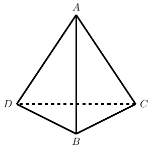
The first step is to determine the symmetry group in play. For the tetrahedron, this is , the group of all permutations on symbols. The four symbols themselves can be see by labelling the vertices as in Figure 1.
The symmetries split into two sets: those that need a reflection and those that don't. The ones that don't correspond to the alternating subgroup, .
My method for finding colourings starts by looking at the orbits of each type of symmetry.
One thing to note is that every symmetry preserves the following three colourings:
-
Monochrome,
-
All edges different,
-
Opposite edges the same.
Although there are lots of symmetries ( in total), they break down into one of types (not counting the identity). To describe them, I'll use standard permutation notation using the vertices as labelled in the earlier diagram, for example is the reflection that swaps and , and I'll refer to edges by listing the vertices at each end, so is the edge between and .
For each, I'm going to pick out a "favourite" colouring. My criteria is that I want to pick the one that I feel best shows off the relevant symmetry. So it might not be the most symmetrical in each set.
-
Four cycle, e.g., .
One way to view this is to picture the tetrahedron looking down on an edge, as in Figure 1. Giving it a quarter turn, say anticlockwise, brings the vertices round so that is above where was, is below where was, and so on. Then we reflect the tetrahedron in a horizontal mirror so that descends to exactly where was and ascends to where was.
The orbits of this particular four cycle are:
This means that the pieces we can use to construct a colouring are:
-
or
-
, or , or as singletons
We now do a "Countdown" choice: one from the top and one from the bottom. On the face of it, this gives choices. We actually have a few more because we can potentially combine sets from different rows. So if we choose from the top and from the bottom then we can further decide to keep these separate (two colours) or combine them into one (one colour). When we combine in this fashion we have to check that the result is still fixed by the symmetry, for example if choosing from the top and from the bottom then we can have but not . But then we don't want to double count, so if we've already got then we don't need .
I think2 that this gives the following colourings, in addition to the three that are automatically there.
2It's entirely possible that I've mislaid some.
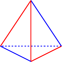
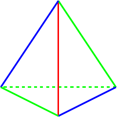
Of these, I think that the last is my favourite for this symmetry. While the first does show the four cycle (particularly when viewed from above either or ), I think that the last is better because it shows that the four cycle isn't simply a quarter turn but also involves a reflection. This is shown in Figure 2.
-
-
Three cycle, e.g., .
This is a rotation about an axis through a vertex, in this case . The orbits of this particular three cycle are:
So our pieces for constructing a colouring are:
-
or
-
or
Again, modulo me having missed one (and not listing the ones that are always there), I get:
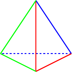
For showing off the three cycle, I think I would pick the last, shown in Figure 3. It looks like arrows around the tetrahedron so clearly indicates the rotation.
-
-
Two cycle, e.g., .
This is a reflection in the plane containing the edge . The orbits of this are:
For choosing a colouring, therefore, we have the following sets:
-
-
-
or
-
or
Although we only get four directly (one of which is one of the standard ones), there are quite a few ways of coordinating colours by combining groups so this results in quite a few colourings. Since the edges and are invariant under the symmetry, they can be added to any pair to create a new colouring. They can't be added to another singleton (other than combining with ) since if, say, and were the same colour then would also have to be that colour.
I feel this is the one where I'm most likely to have missed one out!
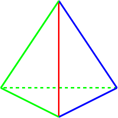
Picking a favourite here is tricky because a two cycle is very little by way of symmetry so to "show off" a two cycle involves picking one with little symmetry. I'm choosing two to show this: and . I think that the first makes the symmetry (or lack of it) very clear while the second, which is shown in Figure 4, is better if you want to hide the fact that it only has reflective symmetry.
-
-
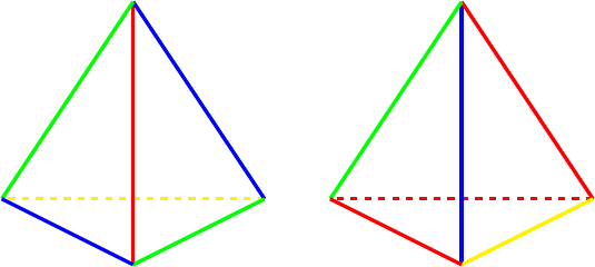
A pair of transpositions, e.g., .
This is a rotation (half turn) about the centre of an edge, in this case and . The orbits are:
So the starting pieces of our colourings are the sets:
-
-
.
-
or .
-
or .
This symmetry is related to the four cycle above: doing the four cycle twice results in this one. So any colouring that works for the four cycle will also work for this one, and therefore I will focus on the additional colourings that this symmetry brings. This means breaking the symmetry between the pairs and so we only have colourings where these two are treated differently.
To illustrate this symmetry, and avoid the four cycle symmetry, I think I would go for the first colouring in this list. This is shown in Figure 5.
-
My "favourite" colourings in the above list were motivated by illustrating a given symmetry. However my original motivation for doing this was starting at the other end where I have a particular set of designs to use, so number of colours is the more likely starting point. With that in mind, here are my favourites for a given number of colours.
-
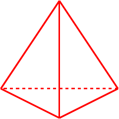
One colour, Figure 6. Not much choice here!
-
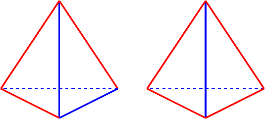
Two colours, Figure 7. A few options here.
-
, the four cycle symmetry is possibly the least obvious in the symmetries of a tetrahedron.
-
, the most common views of a tetrahedron have it sitting on a base triangle, this encourages balancing it on an edge.
-
-
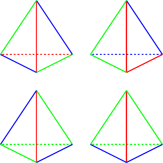
Three colours, Figure 8.
-
, has full symmetry. Also nicely shows the action of on three objects.
-
, this emphasises the three cycle as it looks like arrows pointing around the tetrahedron.
-
.
-
, looks like it has a lot of symmetry, actually has very little!
-
-
Four colours, Figure 9.
With four colours, the symmetries start to get a little lost in the plethora of design. So with four colours I might look at emphasising some other aspect of the tetrahedron.
-
, this is probably the most symmetrical with four colours.
-
. This puts the focus on a Hamiltonian path round the vertices of the tetrahedron. If the colour used for the three edges is very distinct from the others, this can be more effective.
-
-
Five colours.
With five colours you have just two edges the same colour so there are only two actual colourings: where the two are adjacent and where they are opposite. With the two adjacent, this emphasises the two cycle symmetry and with the two opposite the four cycle symmetry. However, I would have to admit that I'm not keen on either as I suspect both will look like the coincidence of colour was just that: a coincidence.
-
Six colours.
Only one possibility here!
3 From Origami to Graphs
Before looking at the other polyhedra, I want to introduce something that I've found very useful when working with more complicated shapes: graphs.
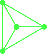
As we are only concerned with the edges of the model we can open it out to a flat diagram, called a graph. The standard way to picture this is to view the edges as drawn on the surface of a sphere made of some flexible material, then puncturing the sphere in the middle of a face and stretching it out so that it is flat. If you have trouble seeing this, I suspect that there are innumerable videos of it on the internet.
The tetrahedron is the simplest and is shown in Figure 10. Here it is possible to actually see the tetrahedron, though note that the fourth face is not hidden behind the obvious three but constitutes the outside region.
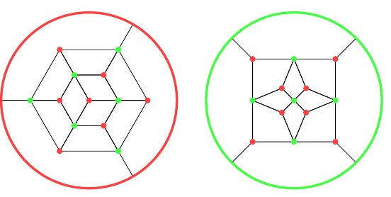
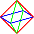
The octahedron and cube are dual, and it turns out to be useful to superimpose the graphs as in Figure 11. In the following, the octahedron is in green and the cube in red. The graph for the octahedron is formed first. The outermost face is outside the graph and its edges are the arcs. The graph of the cube is created by placing a vertex at the centre of each face of the octahedron. Since one of these vertices is outside the graph of the octahedron, we use the convention that it is "at infinity" and any edge heading off out of the drawing region ends at this vertex.
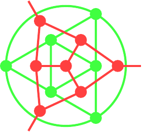
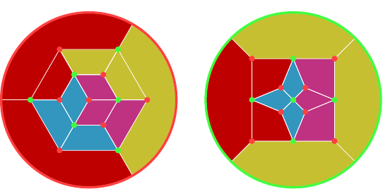
Starting with the graph of the octahedron with its dual, we can design a different graph, shown in Figure 12, by taking all the vertices of the two graphs and then joining them in such a fashion that the edges in the original graphs form regions in the new. The vertex "at infinity" is represented by the outer circle. To recover the original graph for one of the polyhedra, keep the vertices of a given colour and then join any two that lie opposite in a region. The one on the left has a vertex of the cube at its centre, the one on the right a vertex of the octahedron. With the convention that the outer circle represents a single vertex, these two are the same graph but by choosing different centres each makes it easier to see certain symmetries. I find it easier to use the layout on the left for designing an octahedron and the one on the right for a cube.
One reason that this is a useful representation of the polyhedra is that because the edges are now regions, they can be coloured by actually colouring them in. Although the symmetries are a little harder to see, trying out different colourings becomes simpler.
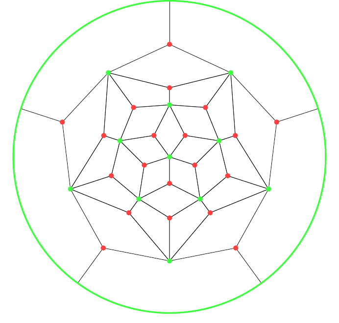
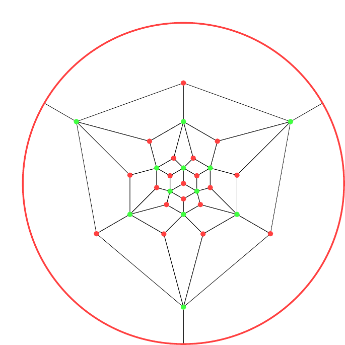
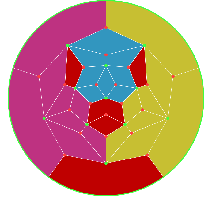
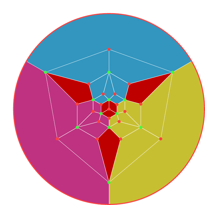
Here are the graphs for the dodecahedron, Figure 13, and icosahedron, Figure 14. The red vertices are from the dodecahedron and the green from the icosahedron. The first has a vertex of the icosahedron at its centre, and so I find it more suitable for colouring a dodecahedron.
4 Cube and Octahedron
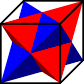
The symmetry group of the cube and octahedron is , with the determining whether or not a reflection is used. The is interesting and there are a variety of ways to see it. One that I find intriguing is that there are two interlocked tetrahedra inside a cube, as shown in Figure 15. Any symmetry of the cube therefore induces a symmetry of a tetrahedron, possibly with a reflection to swap between the two. By allowing ourselves to swap the tetrahedra, we can realise every symmetry of a tetrahedron by an orientation-preserving symmetry of the cube.
Another way to see the is to colour the faces of an octahedron (alternatively, to colour the corners of a cube) as shown in Figure 16. Hold an octahedron so that you are looking at a vertex and four faces are visible to you. Label each face with a symbol – or colour it – and label its opposite face with the same symbol.
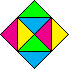
What is now true is that for any ordering of the symbols there is an orientation of the octahedron so that you see that ordering. In the figure above, each vertex has a different cyclical order of the colours. For example, the central vertex has and the upper right one has .
Let's now look at colourings. As with the tetrahedron, we start by listing those colourings that are preserved by all symmetries. We will describe them as for a cube.
-
Monochrome,
-
All edges different,
-
Opposite edges the same,
-
Edges opposite across a face the same.
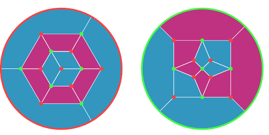
The latter can also be described as saying that all edges that point in the same direction have the same colour as each other. When viewed on an octahedron, in Figure 17, this colouring is particularly pleasing.
On the colouring graph, this looks like Figure 18.
I shan't go through the full analysis for the cube as I did for the tetrahedron. With twelve edges, it gets too complicated when all I want is some starting points for a given number of colours. There's also the question for each colouring as to whether it works best on the cube or the octahedron.
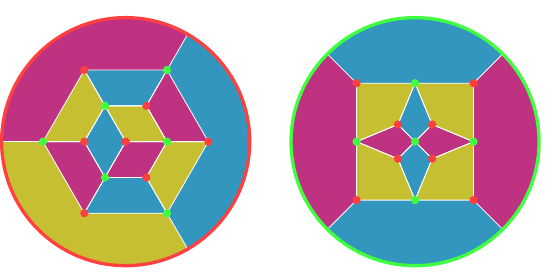
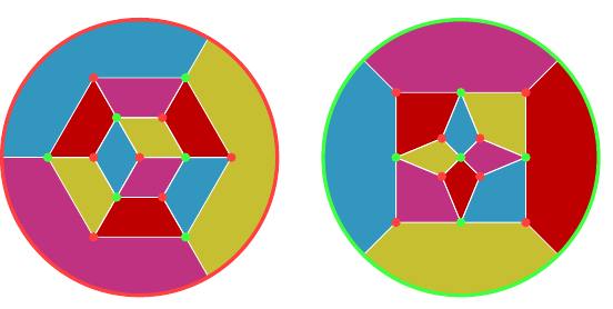
With three colours already dealt with in Figure 18, I'll start with four colours. Since the edges of a cube nicely divide into three groups of four by direction, we can exploit this when looking at colouring them with four colours and pick one from each group for each colour. So for a given colour we have three edges that all align in different directions. We get variations on this theme by picking how the three edges are related. An easy option is to have them joined together, either at a single vertex (on the cube, on the octahedron they would encircle a face) shown in Figure 19 or by making a path, shown in Figure 20.
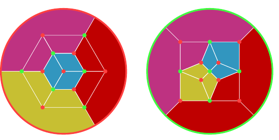
Remember that the red dots are vertices of the cube and the green are vertices of the octahedron.
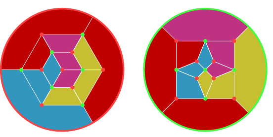
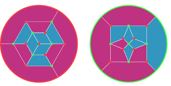
A slightly simpler one, in Figure 21, echos the "pointing arrows" on the three colouring of the tetrahedron.
Instead of choosing the edges next to each other, we could choose them so that they don't join, as shown in Figure 22.
Two colourings can be obtained from four colourings by pairing the colours used. In Figures 23 and 24 are a couple of other two colourings that emphasise the symmetries of the cube and octahedron.
I think that with five colours I would make all but one face (of the cube) monochrome and then use the remaining four colours around that face. Alternatively, use one colour to trace out a Hamiltonian circuit (which uses eight edges) and then use the other colours for the remaining edges.
With six, I would start by colouring each direction with one colour and then replace just one edge in each direction by a second colour, and I would choose them so that the recoloured edges don't touch.
Beyond six, I feel it is getting too crowded to use the colours to reveal any particular structure.
5 Icosahedron and Dodecahedron
The symmetry group of the icosahedron and dodecahedron is , with the alternating group as the symmetries that don't need a reflection. This is somewhat harder to see but there is some obvious structure. Rotating around a face of the dodecahedron is a –cycle, while rotating around a face of the icosahedron is a –cycle. Rotating through the centre of an edge has order , but is not a –cycle (as that would be an odd transposition and so need a reflection). Another thing that is easy to see is that the order of the symmetry group is correct. There are thirty edges on an icosahedron and the symmetry group acts transitively on the edges, then we can rotate about the mid point of an edge which brings us to symmetries and these are all the ones achievable with just rotations. Finally, reflection along the edge brings the count to .
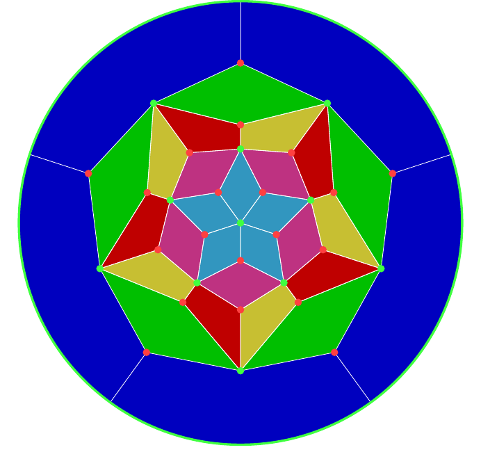
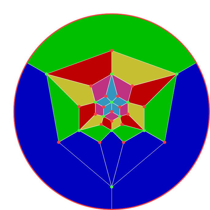
I'll dive right in with the colourings because there's a really neat edge colouring that shows much of the structure, shown in Figures 25 and 26. At every vertex of the icosahedron (equivalently, face of the dodecahedron) there are five edges. The colouring is such that each of these sets of five edges gets coloured with the five colours and is such that at every vertex the (cyclic) ordering is unique. There are such cyclic orderings: by listing them with a fixed starting colour then the order of the remaining four colours gives a copy of . The twelve vertices of the icosahedron then correspond to half of these cyclic orderings, corresponding to the action of inside . So the action of inside can be seen by rotating the icosahedron to bring a particular vertex to the fore, and then rotating about that vertex. This gives orientations.
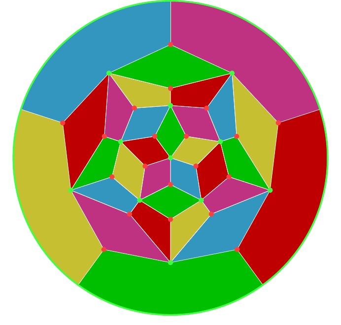
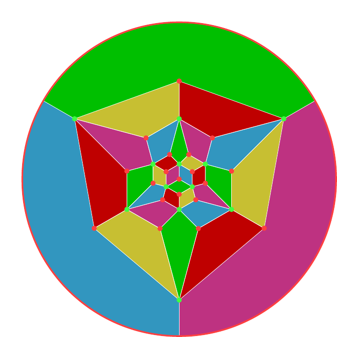
When colouring with three or six colours we can exploit a curious feature of the icosahedron. It has twelve vertices and each vertex has valency five. If we draw a path along the edges, that path will have two end points and several midpoints. At each midpoint it uses up two edges. At each endpoint, it uses up one. Since each vertex has odd valency, if we draw disjoint paths that use up every edge, we must have at least twelve end points, meaning six paths. If this is possible we can then use this to colour the edges using six colours.
Of course it is possible. I wouldn't have mentioned it if it weren't. Figures 27 and 28 show it in the two different layouts.
Careful inspection will show that the colours come in pairs which don't meet. Therefore this also gives a nice colouring with three colours by using the same colour for opposite paths.
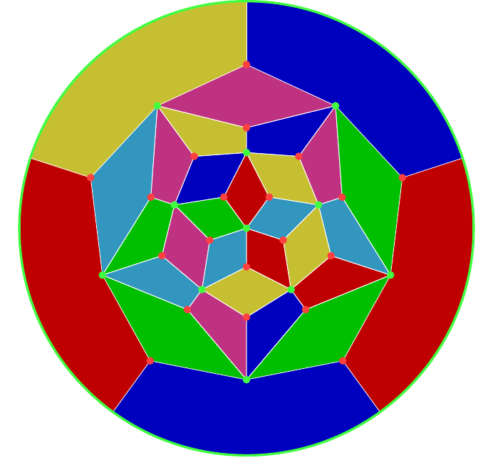
Two and four colours is more tricky. Four is especially so because even though there are four cycles in the symmetry group, the number of edges isn't divisible by four and so it isn't possible to find four sets of edges that will be cycled through under a four cycle. Instead, I've gone for a trick: think of four as and use three colours to illustrate an –symmetry with the fourth colour filling in the gaps. To this end, in Figures 29 and 30 I've gone for three groups of eight and one group of six.
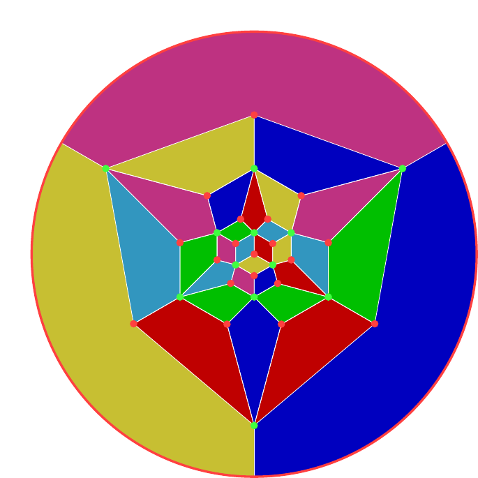
The system I've found for two colours is to look at "lines of latitude". That is, to hold the polyhedron (whether icosahedron or dodecahedron) with a definite north and south pole and then look at edges that are on the same level as each other. These provide six groups of five (well, the equator is really a group of ten but it can be split into two by looking at the slant direction of the edges). Splitting these groups into two provides a variety of two colourings. Note that the split doesn't have to be equal: splits into ten and twenty can be as pleasing as into fifteen and fifteen. Figure 31 and 32 show the groupings.
6 Final Remarks
One of the underlying themes of this approach is that when making a polyhedron using modular origami then the modules represent the edges of the model (most of the time). Sometimes, though, a symmetry seems to play better with the focus on the vertices or faces. For example, the symmetries of the tetrahedron seem more natural when viewed as acting on the vertices.
So it is fortunate that there are a couple of tricks to play to allow the focus to shift from the edges: truncation and stellation.
Truncation is where the vertices are sliced off by some amount. The amount can vary to produce a few different polyhedra. What this does is allow the focus to be on the vertices because each vertex in the original polyhedron now becomes a face in the new one, and these faces don't share edges so each can be coloured independently. If the truncation is maximal, none of the original edges are present in the new model.
Stellation is where the faces are subdivided, usually by adding a new vertex in the centre and joining it to each of the original vertices around that face. The new vertex is usually shifted in or out of its original face as well. This provides a new set of edges which correspond to the faces and so can be coloured accordingly. The original edges are usually still present with stellation, though there are stellations where it is possible to remove them.
In both cases, if the original edges are present then one option is to keep them a single colour. This will draw the focus to the edges introduced by the truncation or stellation.
Lastly, symmetry is all very well but sometimes the best way to draw attention to something is for it to be absent, but obviously absent. So one could start with a symmetric design as I've described and then break it by changing one edge, or one group of edges.